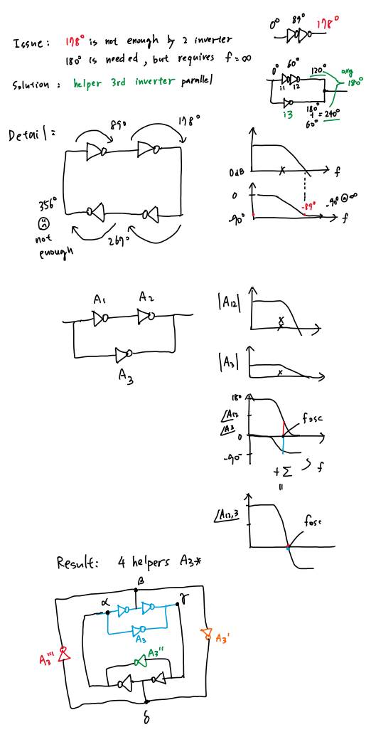
- 1 · The idea in one line
- 2 · 🔑 Key simulation results
- 3 · 📉 Even 4-stage ring — "356°, not enough"
- 4 · ✅ Odd 3-stage ring — phase sum sets f_osc
- 5 · 🐍 Python model source
- 6 · 🔬 SkyWater sky130 transistor-level simulation
- 7 · 🔁 8-inverter "4-helper" ring — 4-net oscillator
- 8 · 🧾 Complete code to reproduce
- 9 · 🧭 Mistakes & Corrections
| # | Quantity | Condition | Simulated value | Verdict |
|---|---|---|---|---|
| 1️⃣ | Even 4-stage ring | needs −360° from poles | −356° @ 57 GHz | ❌ never (only at ∞) |
| 2️⃣ | Odd 3-stage ring | needs −180° from poles | −60°/stage → −180° | ✅ f_osc = 1.732 GHz |
| 3️⃣ | Loop gain at f_osc | |H| = A0/2 = 2.0 | |L| = 2³ = 8 | ✅ ≥ 1 |
| 4️⃣ | Min DC gain / stage | (A0/2)³ ≥ 1 | A0 ≥ 2.0 | design floor |
🖱️ Hover to read the angle at any frequency — a vertical line follows the cursor and the unified tooltip labels each curve. The red curve tops out near −360° but never reaches it.
🖱️ Hover the bottom panel: the total phase ∠A123 crosses the −180° line exactly at the azure marker → f_osc = 1.732 GHz, where each stage contributes −60° and loop gain |L| = 8.
ring_osc_model.py
"""
Ring-oscillator phase model  (Barkhausen / phase-shift view)
============================================================
Reproduces the two hand-sketch scenarios:

  (A) EVEN 4-stage ring  -> "356 deg, not enough" : never oscillates
  (B) ODD  3-stage ring  -> phase sum crosses -180 deg at f_osc : oscillates

Model of ONE inverting gain stage (single dominant pole):

        H(jw) = -A0 / (1 + j*w/wp)

    - the "-" sign  = 180 deg DC inversion (frequency independent)
    - the pole      = extra lag  phi_pole(w) = -atan(w/wp)
      which only reaches -90 deg as w -> infinity.

Loop (N identical stages):  L = H^N
Oscillation (Barkhausen):   angle(L) = -360 deg  AND  |L| >= 1

    N inversions give N*180 deg.  The pole lag must supply the rest.
      N=3 : 540 deg  ->  need 3*(-60 deg) = -180 deg  (reachable, finite f)
      N=4 : 720 deg  ->  need 4*(-90 deg) = -360 deg  (only at inf -> fails)
"""

import numpy as np

# ---- stage parameters (popular / realistic numbers) --------------------
A0   = 4.0            # DC gain per stage (V/V)  -> 20*log10(4) = 12.04 dB
fp   = 1.0e9          # dominant pole of one inverter stage = 1 GHz
DEG  = 180.0 / np.pi

# frequency sweep: 0.01*fp ... 100*fp  (log spaced)
f  = np.logspace(np.log10(0.01*fp), np.log10(100*fp), 1500)
w  = 2*np.pi*f
wp = 2*np.pi*fp
x  = w/wp                     # normalized frequency f/fp

# ---- one stage ---------------------------------------------------------
mag_stage_dB   = 20*np.log10(A0/np.sqrt(1 + x**2))       # |H| in dB
phi_pole_stage = -np.arctan(x)*DEG                       # pole lag only, deg (0 -> -90)

# =======================================================================
# (A) EVEN 4-STAGE RING
# =======================================================================
N4 = 4
phi_pole_4 = N4*phi_pole_stage          # cumulative pole lag of 4 stages (0 -> -360)
# required cumulative pole lag to oscillate for the even ring = -360 deg
# -> impossible at finite f. Show how close we get at top of sweep.
f_hi           = np.tan(np.deg2rad(89))*fp   # probe freq giving 89 deg/stage (matches sketch)
x_hi           = f_hi/fp
phi_stage_hi   = -np.arctan(x_hi)*DEG    # ~ -87.1 deg  ("89-ish, not 90")
phi_4_hi       = N4*phi_stage_hi         # ~ -356 deg   ("not enough")

# =======================================================================
# (B) ODD 3-STAGE RING  (decomposed as A12 = 2 stages, A3 = 1 stage)
# =======================================================================
N3 = 3
phi_A12 = 2*phi_pole_stage               # two-stage cascade pole lag  (0 -> -180)
phi_A3  = 1*phi_pole_stage               # one-stage pole lag          (0 -> -90)
phi_sum = phi_A12 + phi_A3               # total pole lag = 3 stages    (0 -> -270)

# Oscillation: total pole lag = -180 deg  ->  atan(x) = 60 deg  ->  x = tan60 = sqrt(3)
x_osc   = np.tan(np.deg2rad(60))         # = sqrt(3) = 1.7320
f_osc   = x_osc*fp                        # = sqrt(3) * fp  = 1.732 GHz
# per-stage phase & loop gain at f_osc
phi_stage_osc = -np.arctan(x_osc)*DEG                    # -60.0 deg exactly
mag_stage_osc = A0/np.sqrt(1 + x_osc**2)                 # |H| at f_osc  = A0/2
loop_gain_osc = mag_stage_osc**N3                        # |L| at f_osc
Amin          = 2.0                                      # min DC gain/stage for 3-ring

# magnitude curves for the decomposition plot
mag_A12_dB = 2*mag_stage_dB
mag_A3_dB  = 1*mag_stage_dB

if __name__ == "__main__":
    print("=== stage ===")
    print(f"A0 = {A0}  ({20*np.log10(A0):.2f} dB),  fp = {fp/1e9:.3f} GHz")
    print("\n=== (A) even 4-stage ring ===")
    print(f"per-stage lag at {f_hi/1e9:.0f} GHz = {phi_stage_hi:6.2f} deg  (-> -90 only at inf)")
    print(f"4-stage cumulative lag         = {phi_4_hi:6.2f} deg  (need -360 -> NOT ENOUGH)")
    print("\n=== (B) odd 3-stage ring ===")
    print(f"x_osc = f_osc/fp = tan(60) = {x_osc:.4f}")
    print(f"f_osc = {f_osc/1e9:.4f} GHz")
    print(f"per-stage phase at f_osc = {phi_stage_osc:.2f} deg")
    print(f"total pole lag at f_osc  = {phi_A12[np.argmin(abs(f-f_osc))]+phi_A3[np.argmin(abs(f-f_osc))]:.2f} deg (target -180)")
    print(f"|H| at f_osc = A0/2 = {mag_stage_osc:.3f}")
    print(f"|L| = |H|^3 at f_osc = {loop_gain_osc:.3f}  (>=1 oscillates)")
    print(f"min DC gain/stage for sustained osc = {Amin}")
Model: single dominant-pole inverter, H(jω) = −A₀/(1+jω/ω_p). Frequencies normalized to f_p = 1 GHz; charts use Plotly (log-frequency axis, cursor spike lines, unified hover).
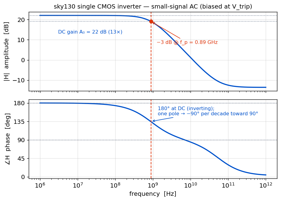
The single-pole model above is confirmed against real transistors: a CMOS inverter built from
sky130 core devices (sky130_fd_pr__pfet_01v8 / nfet_01v8, 1.8 V), wired into 3- and
4-stage rings and simulated in ngspice (tt corner, 27 °C). Every number and curve below is a live
ngspice result — the exact decks are in Section 7.
Single-inverter response — the building block. One sky130 inverter's small-signal AC, biased at its switching threshold (Vtrip = 0.87 V) — a single-pole inverting gain stage:
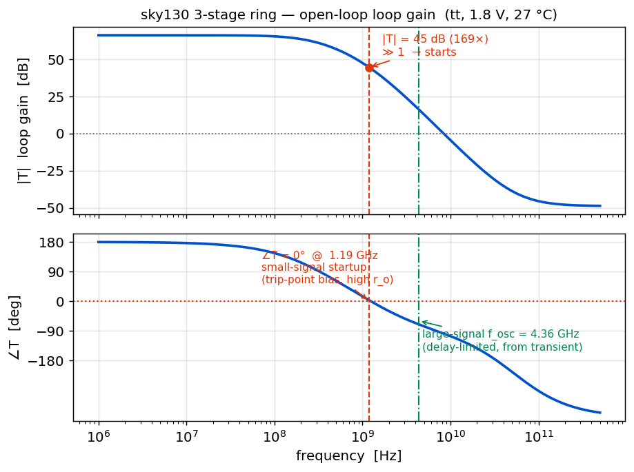
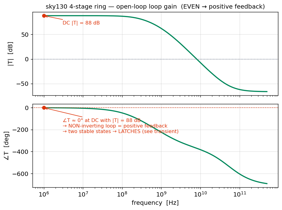
AC — open-loop loop gain (frequency & phase response). This replicates the §3/§4 Bode diagrams with real devices:
Transient — closed-loop, at the bottom. Let the rings run and watch the time-domain behaviour:
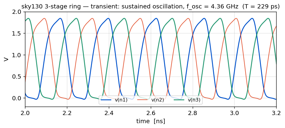
- The loop-gain AC is a small-signal analysis, linearised at the switching threshold. The DC loop (closed through the 1 MH inductor) biases every inverter at Vtrip ≈ 0.87 V — verified in the .op. There both devices are saturated, so the output resistance is at its maximum (ro ≈ 30 kΩ measured), giving the lowest pole, fp ≈ 0.69 GHz. Three poles reach −180° at 1.73·fp = 1.19 GHz. That is the frequency at which oscillation starts from noise.
- The real oscillation is large-signal / slewing. Once it swings rail-to-rail, each stage switches with its devices in triode (Ron ≈ 8 kΩ, ~4× lower than ro), so the delay is short (td = 38 ps) and fosc = 1/(2N·td) = 4.36 GHz. The ro/Ron ≈ 4 ratio is exactly the 3.7× frequency ratio.
- So it is a physics distinction, not a model error. The sky130
nfet_01v8/pfet_01v8devices are used correctly; a ring oscillator is inherently a large-signal circuit, and no single-bias small-signal AC can predict its steady-state frequency. The delay-based fosc = 1/(2N·td) is the right predictor — and it matches the transient to the digit.
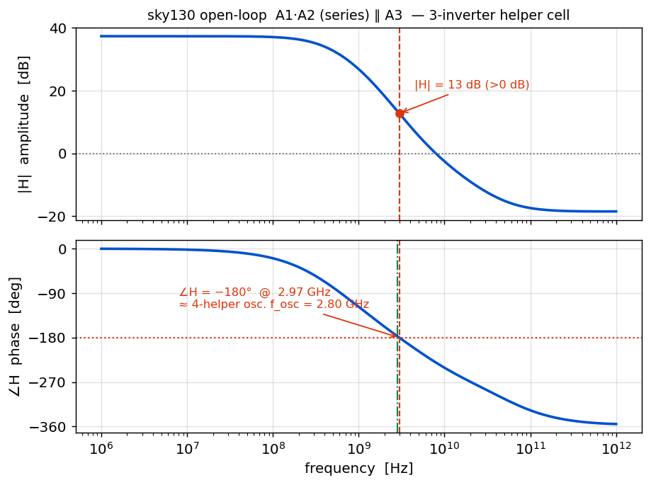
Open-loop response of the helper cell — A1·A2 (series) ∥ A3. This is the building block the 4-helper oscillator (§7) is made of: two inverters in series, in parallel with a single helper A3 (outputs shorted, the "phase-averaging" node). Its open-loop amplitude & phase directly predict the oscillation frequency:
| Ring | Parity | Small-signal startup (∠T=0°) | Loop gain there | Large-signal transient |
|---|---|---|---|---|
| 3-stage | odd → inverting | 1.19 GHz | 45 dB (169×) | oscillates, fosc = 4.36 GHz |
| 4-stage | even → non-inverting | — (0° only at DC) | 88 dB at DC | latches (bistable) |
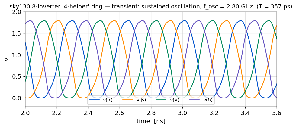
The hand sketch's "Result: 4 helpers A₃" circuit is not a simple chain — it has only four nets (α, β, γ, δ) wired symmetrically: a distance-1 ring α→β→γ→δ→α (A1, A2, A4, A5) plus four helper diagonals — α→γ (A3), γ→α (A3″), β→δ (A3′), δ→β (A3‴). Every net is driven by two inverter outputs (shorted together) and drives two — the "phase-averaging" the sketch is about. I built this exact 4-net topology in sky130 ngspice.
Transient — closed loop:
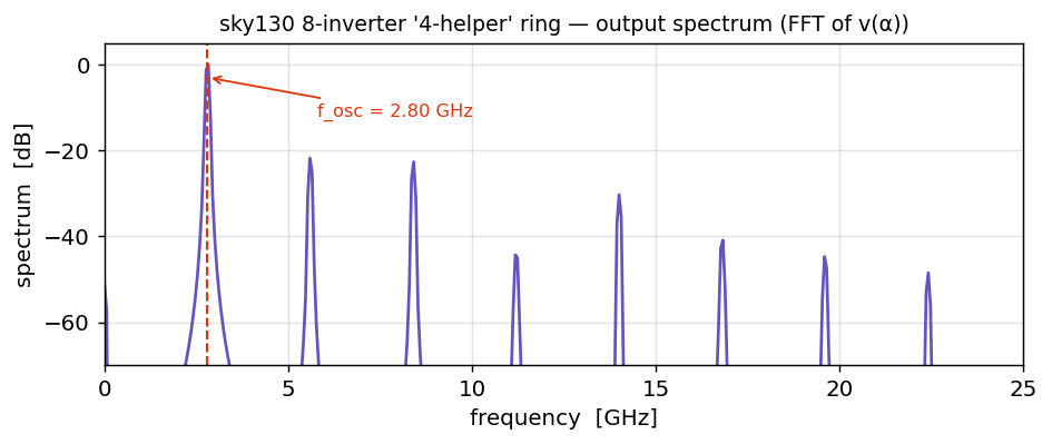
Frequency content — FFT of the output:
Summary — 3-inverter vs 8-inverter (both real sky130 ngspice)
| Metric | 3-inverter ring (§6) | 8-inverter "4-helper" ring |
|---|---|---|
| Topology | simple odd ring | 4 nets (α,β,γ,δ): ring + 4 helper diagonals |
| Inverters | 3 | 8 |
| Transient behaviour | sustained oscillation | sustained oscillation (4-phase) |
| Oscillation frequency | fosc = 4.36 GHz | fosc = 2.80 GHz |
| Period T | 229 ps | 357 ps |
| Output phases | 3 (120° apart) | 4 (~90° apart) |
| Verdict | ✅ oscillator | ✅ oscillator, ~1.6× slower |
Takeaway: the extra stages and helper diagonals lower fosc from 4.36 GHz to 2.80 GHz (~1.6×) and turn the 3-phase ring into a symmetric 4-phase oscillator — more inverters and more feedback paths buy lower frequency and more output phases, at the cost of area and power.
Everything needed to regenerate every curve above from scratch. Files live in sky130_sim/. The netlists carry a __LIBPATH__ placeholder that run.sh substitutes with your local sky130 model path.
📄 Environment setup (macOS / Linux)
# 1. ngspice
brew install ngspice          # macOS   (Linux: apt install ngspice)

# 2. sky130 device models via volare
pip install volare matplotlib numpy
volare enable --pdk sky130 c6d73a35f524070e85faff4a6a9eef49553ebc2b
#   -> models land in:
#   ~/.volare/volare/sky130/versions/<sha>/sky130A/libs.tech/ngspice/sky130.lib.spice

# 3. run everything (decks + plots)
cd sky130_sim
./run.sh
📄 inv.spice — sky130 CMOS inverter
* sky130 CMOS inverter subcircuit (1.8 V core devices)
* PFET sized 2x NFET so the switching threshold sits near VDD/2.
.subckt inv in out vdd vss
XMP out in vdd vdd sky130_fd_pr__pfet_01v8 L=0.15 W=2.0 nf=1 m=1
XMN out in vss vss sky130_fd_pr__nfet_01v8 L=0.15 W=1.0 nf=1 m=1
* small explicit load so every stage sees a realistic fan-out cap
Cload out vss 5f
.ends inv
📄 ac_single_inverter.spice — single inverter, small-signal AC
* ================================================================
*  Single sky130 CMOS inverter — small-signal AC amplitude & phase.
*  Biased at its switching threshold (self-bias via a big inductor,
*  DC-closed / AC-open), stimulus injected at the input.
*  H(f) = V(out)/V(in)  — a single-pole inverting gain stage:
*  |H|(0) = A0, phase = 180deg at DC, rolling to +90 (=-270) as f->inf.
* ================================================================
.lib "__LIBPATH__" tt
.include "inv.spice"

.param SUP=1.8
Vdd vdd 0 {SUP}

Xinv in out vdd 0 inv
Lbias out in 1e6            ; DC self-bias to Vtrip, AC-open
Cinj nac in  1e6
Vac  nac 0   dc 0 ac 1

.control
  op
  print v(in) v(out)
  ac dec 60 1e6 1e12
  let hmag = db(v(out))
  let hph  = 180/PI * ph(v(out))
  wrdata ac_single_inverter.txt hmag hph
.endc
.end
📄 ac_loopgain_3stage.spice — odd ring, open-loop AC
* ================================================================
*  sky130 3-stage ring oscillator  --  OPEN-LOOP loop-gain (AC)
*  Replicates the phase-shift Bode diagram with real transistors.
*
*  Loop-break method (inductor / coupling-cap):
*    - Lbrk closes the loop at DC, so every stage self-biases to its
*      own switching threshold (the true ring operating point), but
*      is OPEN at AC -> the loop is broken for the small-signal test.
*    - Cinj (huge) injects the AC stimulus into n1 at AC only.
*    - With V(n1)=1<0 at AC, the measured loop gain is T = V(n3o).
*  Oscillation (Barkhausen): |T| >= 1 where /_T = 0 deg (mod 360).
* ================================================================
.lib "__LIBPATH__" tt
.include "inv.spice"

.param SUP=1.8
Vdd vdd 0 {SUP}

* --- three inverter stages: n1 -> n2 -> n3 -> n3o ---
Xi1 n1  n2  vdd 0 inv
Xi2 n2  n3  vdd 0 inv
Xi3 n3  n3o vdd 0 inv

* --- loop break: DC-closed (bias), AC-open ---
Lbrk n3o n1  1e6
* --- AC injection into n1 (DC-blocked) ---
Cinj nac n1  1e6
Vac  nac 0   dc 0 ac 1

.control
  ac dec 60 1e6 5e11
  let tmag = db(v(n3o))
  let tph  = 180/PI * ph(v(n3o))
  wrdata ac_loopgain_3stage.txt tmag tph
  print "--- 3-stage open-loop scan done ---"
.endc
.end
📄 ac_openloop_A12parA3.spice — helper cell A1·A2 ∥ A3, open-loop amplitude/phase
* ================================================================
*  Open-loop transfer of the parallel-helper 3-inverter cell:
*    A1,A2 in SERIES (xin -> xmid -> yout) in PARALLEL with A3 (xin -> yout).
*  A2 and A3 outputs are shorted at yout (current summing = phase averaging).
*  Loop broken with Lbrk (DC-closed for bias, AC-open); stimulus at xin.
*  H(f) = V(yout)/V(xin).  We look for the 180-deg crossing.
* ================================================================
.lib "__LIBPATH__" tt
.include "inv.spice"

.param SUP=1.8
Vdd vdd 0 {SUP}

Xa1 xin  xmid vdd 0 inv      ; A1
Xa2 xmid yout vdd 0 inv      ; A2   (A12 = A1.A2 in series)
Xa3 xin  yout vdd 0 inv      ; A3   parallel helper, shorted at yout

Lbrk yout xin 1e6
Cinj nac  xin 1e6
Vac  nac 0    dc 0 ac 1

.control
  op
  print v(xin) v(yout) v(xmid)
  ac dec 80 1e6 1e12
  let hmag = db(v(yout))
  let hph  = 180/PI * ph(v(yout))
  wrdata ac_openloop_A12parA3.txt hmag hph
.endc
.end
📄 ac_loopgain_4stage.spice — even ring, open-loop AC
* ================================================================
*  sky130 4-stage ring  --  OPEN-LOOP loop-gain (AC)
*  EVEN number of inversions -> net NON-inverting loop.
*  DC loop gain is positive and huge (~88 dB) -> two stable states
*  -> the ring LATCHES; it is NOT a frequency-domain oscillator.
*  (Same loop-break method as the 3-stage deck.)
* ================================================================
.lib "__LIBPATH__" tt
.include "inv.spice"

.param SUP=1.8
Vdd vdd 0 {SUP}

Xi1 n1  n2  vdd 0 inv
Xi2 n2  n3  vdd 0 inv
Xi3 n3  n4  vdd 0 inv
Xi4 n4  n3o vdd 0 inv

Lbrk n3o n1  1e6
Cinj nac n1  1e6
Vac  nac 0   dc 0 ac 1

.control
  ac dec 60 1e6 5e11
  let tmag = db(v(n3o))
  let tph  = 180/PI * ph(v(n3o))
  wrdata ac_loopgain_4stage.txt tmag tph
.endc
.end
📄 tran_3stage.spice — odd ring, transient (oscillates)
* ================================================================
*  sky130 3-stage ring oscillator  --  CLOSED-LOOP transient
*  Odd ring -> no stable static state -> sustained oscillation.
*  .ic kicks it off the metastable point; it self-starts from there.
* ================================================================
.lib "__LIBPATH__" tt
.include "inv.spice"

.param SUP=1.8
Vdd vdd 0 {SUP}

* --- closed 3-stage ring: n1 -> n2 -> n3 -> n1 ---
Xi1 n1 n2 vdd 0 inv
Xi2 n2 n3 vdd 0 inv
Xi3 n3 n1 vdd 0 inv

* seed the loop away from the Vtrip metastable point
.ic v(n1)=0 v(n2)=1.8 v(n3)=0

.control
  tran 1p 12n uic
  wrdata tran_3stage.txt v(n1) v(n2) v(n3)
  * measure the oscillation period from settled cycles (rising-edge crossings @ 0.9 V)
  meas tran t1 when v(n1)=0.9 rise=3
  meas tran t2 when v(n1)=0.9 rise=4
  let Tosc = t2 - t1
  let Fosc = 1/Tosc
  print Tosc Fosc
.endc
.end
📄 tran_4stage.spice — even ring, transient (latches)
* ================================================================
*  sky130 4-stage ring  --  CLOSED-LOOP transient  (EVEN = latch)
*  Even # of inversions -> net NON-inverting loop -> positive
*  feedback -> two stable states. It LATCHES, it does not oscillate.
*  ("178 deg x2 = 356 deg, not enough" -> no sustained oscillation.)
* ================================================================
.lib "__LIBPATH__" tt
.include "inv.spice"

.param SUP=1.8
Vdd vdd 0 {SUP}

* --- closed 4-stage ring: n1 -> n2 -> n3 -> n4 -> n1 ---
Xi1 n1 n2 vdd 0 inv
Xi2 n2 n3 vdd 0 inv
Xi3 n3 n4 vdd 0 inv
Xi4 n4 n1 vdd 0 inv

* start near the metastable point with a tiny nudge on n1
.ic v(n1)=0.95 v(n2)=0.85 v(n3)=0.95 v(n4)=0.85

.control
  tran 1p 12n uic
  wrdata tran_4stage.txt v(n1) v(n2) v(n3) v(n4)
  print "--- 4-stage transient done ---"
.endc
.end
📄 tran_8stage.spice — 8-inverter 4-net ring, transient (oscillates, 2.80 GHz)
* ================================================================
*  sky130 "4-helper" 8-inverter ring  --  CLOSED-LOOP transient
*  CORRECT topology from the "Result: 4 helpers A3*" sketch:
*    Only 4 nets: alpha(al) beta(be) gamma(ga) delta(de).
*    Distance-1 ring : al->be->ga->de->al   (A1,A2,A4,A5)
*    Distance-2 diags: al->ga, ga->al, be->de, de->be  (A3,A3'',A3',A3''')
*    Each net is driven by 2 inverters (outputs shorted) and drives 2.
* ================================================================
.lib "__LIBPATH__" tt
.include "inv.spice"

.param SUP=1.8
Vdd vdd 0 {SUP}

* --- distance-1 ring ---
Xa1 al be vdd 0 inv       ; A1
Xa2 be ga vdd 0 inv       ; A2
Xa4 ga de vdd 0 inv       ; A4  (black, right)
Xa5 de al vdd 0 inv       ; A5  (black, left)
* --- distance-2 diagonals (the 4 helpers) ---
Xa3 al ga vdd 0 inv       ; A3    (cyan helper)  -> shorted onto gamma
Xa6 ga al vdd 0 inv       ; A3''  (green)        -> shorted onto alpha
Xa8 be de vdd 0 inv       ; A3'   (orange)       -> shorted onto delta
Xa7 de be vdd 0 inv       ; A3''' (red)          -> shorted onto beta

* seed off the metastable point
.ic v(al)=0 v(be)=1.8 v(ga)=1.8 v(de)=0

.control
  tran 1p 20n uic
  wrdata tran_8stage.txt v(al) v(be) v(ga) v(de)
  meas tran t1 when v(al)=0.9 rise=4
  meas tran t2 when v(al)=0.9 rise=6
  let Tosc = (t2 - t1)/2
  let Fosc = 1/Tosc
  print Tosc Fosc
.endc
.end
📄 ac_loopgain_8stage.spice — 8-inverter ring, auxiliary single-node loop-gain cut
* ================================================================
*  sky130 "4-helper" 8-inverter ring  --  OPEN-LOOP loop-gain (AC)
*  CORRECT 4-net topology (alpha beta gamma delta).
*  Loop broken at node alpha: its two drivers (A5,A6) are routed to
*  node "aret"; Lbrk feeds aret->alpha for DC bias (AC-open) and the
*  stimulus is injected into alpha through Cinj.  T = V(aret).
* ================================================================
.lib "__LIBPATH__" tt
.include "inv.spice"

.param SUP=1.8
Vdd vdd 0 {SUP}

* drivers of alpha routed to the return node
Xa5 de aret vdd 0 inv       ; A5  (delta->alpha)
Xa6 ga aret vdd 0 inv       ; A3'' (gamma->alpha)
Lbrk aret al 1e6            ; DC-closed, AC-open
Cinj nac al  1e6
Vac  nac 0   dc 0 ac 1

* rest of the network
Xa1 al be vdd 0 inv
Xa2 be ga vdd 0 inv
Xa4 ga de vdd 0 inv
Xa3 al ga vdd 0 inv
Xa8 be de vdd 0 inv
Xa7 de be vdd 0 inv

.control
  ac dec 60 1e6 5e11
  let tmag = db(v(aret))
  let tph  = 180/PI * ph(v(aret))
  wrdata ac_loopgain_8stage.txt tmag tph
.endc
.end
📄 plot_results.py — figures from the ngspice data
#!/usr/bin/env python3
"""
Plot the sky130 ring-oscillator ngspice results.
Reads the wrdata .txt files produced by the .spice decks and writes PNGs.
Run after: ngspice -b ac_loopgain_3stage.spice  (etc.)
"""
import numpy as np
import matplotlib
matplotlib.use("Agg")
import matplotlib.pyplot as plt

BLUE, RED, GREEN, GREY = "#0052CC", "#DE350B", "#00875A", "#5E6C84"
plt.rcParams.update({"font.size": 11, "font.family": "DejaVu Sans",
                     "axes.grid": True, "grid.alpha": .35, "figure.dpi": 130})

def load(fn):
    d = np.loadtxt(fn)
    return d[:, 0], d[:, 1], d[:, 3]      # freq/time, colA, colB


# ---------- 0. Single inverter — small-signal AC amplitude & phase ----------
fs, ms, ps = load("ac_single_inverter.txt")
ps = np.unwrap(np.radians(ps)) * 180/np.pi
A0 = ms[0]
fp = np.interp(-(A0-3), -ms, fs)       # -3 dB pole
fig, (a1, a2) = plt.subplots(2, 1, figsize=(7.2, 5.2), sharex=True)
a1.semilogx(fs, ms, color=BLUE, lw=2)
a1.axhline(A0, color=GREY, ls=":", lw=1); a1.axhline(A0-3, color=GREY, ls=":", lw=1)
a1.axvline(fp, color=RED, ls="--", lw=1.2); a1.plot(fp, A0-3, "o", color=RED)
a1.annotate(f"DC gain A₀ = {A0:.0f} dB ({10**(A0/20):.0f}×)", (fs[0], A0), (fs[0]*3, A0-9),
            color=BLUE, fontsize=9)
a1.annotate(f"−3 dB @ f_p = {fp/1e9:.2f} GHz", (fp, A0-3), (fp*1.4, A0-14),
            color=RED, fontsize=9, arrowprops=dict(arrowstyle="->", color=RED))
a1.set_ylabel("|H|  amplitude  [dB]")
a1.set_title("sky130 single CMOS inverter — small-signal AC (biased at V_trip)", fontsize=11)
a2.semilogx(fs, ps, color=BLUE, lw=2)
a2.axhline(180, color=GREY, ls=":", lw=1); a2.axhline(90, color=GREY, ls=":", lw=1)
a2.axvline(fp, color=RED, ls="--", lw=1.2)
a2.annotate("180° at DC (inverting);\none pole → −90° per decade toward 90°",
            (fp, 135), (fp*1.5, 150), color=BLUE, fontsize=9,
            arrowprops=dict(arrowstyle="->", color=BLUE))
a2.set_ylabel("∠H  phase  [deg]"); a2.set_xlabel("frequency  [Hz]")
a2.set_yticks([0, 45, 90, 135, 180])
fig.tight_layout(); fig.savefig("fig_ac_single_inverter.png", bbox_inches="tight")
print(f"single inverter: A0={A0:.1f} dB, pole fp={fp/1e9:.2f} GHz, DC phase={ps[0]:.0f} deg")

# ---------- 1. AC loop gain, 3-stage (odd -> oscillates) ----------
f, mag, ph = load("ac_loopgain_3stage.txt")
ph = np.unwrap(np.radians(ph)) * 180/np.pi
# small-signal Barkhausen: phase = 0 deg (mod 360) with |T|>=1
i = np.argmin(np.abs(ph))
fx = np.interp(0, [ph[i-1], ph[i]], [f[i-1], f[i]]) if ph[i] != ph[i-1] else f[i]
mx = np.interp(fx, f, mag)

fig, (a1, a2) = plt.subplots(2, 1, figsize=(7.2, 5.4), sharex=True)
a1.semilogx(f, mag, color=BLUE, lw=2)
a1.axhline(0, color=GREY, ls=":", lw=1)
a1.axvline(fx, color=RED, ls="--", lw=1.2)
a1.plot(fx, mx, "o", color=RED)
a1.annotate(f"|T| = {mx:.0f} dB ({10**(mx/20):.0f}×)\n≫ 1  → starts",
            (fx, mx), (fx*1.4, mx+8), color=RED, fontsize=9,
            arrowprops=dict(arrowstyle="->", color=RED))
a1.axvline(4.364e9, color=GREEN, ls="-.", lw=1.2)
a1.set_ylabel("|T|  loop gain  [dB]"); a1.set_title(
    "sky130 3-stage ring — open-loop loop gain  (tt, 1.8 V, 27 °C)", fontsize=11)
a2.semilogx(f, ph, color=BLUE, lw=2)
a2.axhline(0, color=RED, ls=":", lw=1.2)
a2.axvline(fx, color=RED, ls="--", lw=1.2)
a2.axvline(4.364e9, color=GREEN, ls="-.", lw=1.2)
a2.annotate(f"∠T = 0°  @  {fx/1e9:.2f} GHz\nsmall-signal startup\n(trip-point bias, high r_o)",
            (fx, 0), (fx*0.06, 55), color=RED, fontsize=8.5,
            arrowprops=dict(arrowstyle="->", color=RED))
a2.annotate("large-signal f_osc = 4.36 GHz\n(delay-limited, from transient)",
            (4.364e9, -60), (4.8e9, -150), color=GREEN, fontsize=8.5,
            arrowprops=dict(arrowstyle="->", color=GREEN))
a2.set_ylabel("∠T  [deg]"); a2.set_xlabel("frequency  [Hz]")
a2.set_yticks([-180, -90, 0, 90, 180])
fig.tight_layout(); fig.savefig("fig_ac_3stage.png", bbox_inches="tight")
print(f"3-stage AC: small-signal phase=0 at {fx/1e9:.3f} GHz vs large-signal f_osc 4.36 GHz")

# ---------- 2. AC loop gain, 4-stage (even -> never) ----------
f4, mag4, ph4 = load("ac_loopgain_4stage.txt")
ph4 = np.unwrap(np.radians(ph4)) * 180/np.pi
fig, (a1, a2) = plt.subplots(2, 1, figsize=(7.2, 5.4), sharex=True)
a1.semilogx(f4, mag4, color=GREEN, lw=2); a1.axhline(0, color=GREY, ls=":", lw=1)
a1.plot(f4[0], mag4[0], "o", color=RED)
a1.annotate(f"DC |T| = {mag4[0]:.0f} dB", (f4[0], mag4[0]), (f4[0]*3, mag4[0]-18),
            color=RED, fontsize=9, arrowprops=dict(arrowstyle="->", color=RED))
a1.set_ylabel("|T|  [dB]"); a1.set_title(
    "sky130 4-stage ring — open-loop loop gain  (EVEN → positive feedback)", fontsize=11)
a2.semilogx(f4, ph4, color=GREEN, lw=2)
a2.axhline(0, color=RED, ls=":", lw=1.2)
a2.plot(f4[0], ph4[0], "o", color=RED)
a2.annotate("∠T ≈ 0° at DC with |T| = 88 dB\n→ NON-inverting loop = positive feedback\n"
            "→ two stable states → LATCHES (see transient)",
            (f4[0], ph4[0]), (f4[0]*3, -230), color=RED, fontsize=9,
            arrowprops=dict(arrowstyle="->", color=RED))
a2.set_ylabel("∠T  [deg]"); a2.set_xlabel("frequency  [Hz]")
fig.tight_layout(); fig.savefig("fig_ac_4stage.png", bbox_inches="tight")
print(f"4-stage AC: DC phase {ph4[0]:.0f} deg, DC |T| {mag4[0]:.0f} dB -> positive feedback / latch")

# ---------- 3. Transient, 3-stage (oscillates) ----------
t, n1, n2 = load("tran_3stage.txt")
d = np.loadtxt("tran_3stage.txt"); n3 = d[:, 5]
# period from settled rising crossings @ 0.9 V
def crossings(t, v, th=0.9):
    out = []
    for k in range(1, len(v)):
        if v[k-1] < th <= v[k]:
            out.append(t[k-1] + (th-v[k-1])*(t[k]-t[k-1])/(v[k]-v[k-1]))
    return np.array(out)
cx = crossings(t, n1); cx = cx[cx > 3e-9]
Tosc = np.mean(np.diff(cx)); fosc = 1/Tosc
fig, ax = plt.subplots(figsize=(7.4, 3.4))
ax.plot(t*1e9, n1, color=BLUE, lw=1.6, label="v(n1)")
ax.plot(t*1e9, n2, color=RED, lw=1.2, alpha=.8, label="v(n2)")
ax.plot(t*1e9, n3, color=GREEN, lw=1.6, alpha=.85, label="v(n3)")
ax.set_xlabel("time  [ns]"); ax.set_ylabel("V"); ax.set_xlim(2.0, 3.2)
ax.set_ylim(-0.2, 2.0)
ax.set_title(f"sky130 3-stage ring — transient: sustained oscillation, "
             f"f_osc = {fosc/1e9:.2f} GHz  (T = {Tosc*1e12:.0f} ps)", fontsize=11)
# annotate one period, using two settled crossings inside the 2.0-3.2 ns window
cw = cx[(cx > 2.05e-9) & (cx < 3.1e-9)]
if len(cw) >= 2:
    ax.annotate("", (cw[0]*1e9, 1.92), (cw[1]*1e9, 1.92),
                arrowprops=dict(arrowstyle="<->", color=GREY))
    ax.text((cw[0]+cw[1])/2*1e9, 1.95, f"T = {Tosc*1e12:.0f} ps",
            ha="center", va="bottom", fontsize=9, color=GREY)
ax.legend(ncol=3, fontsize=9, loc="lower center")
fig.tight_layout(); fig.savefig("fig_tran_3stage.png", bbox_inches="tight")
print(f"3-stage transient: f_osc = {fosc/1e9:.3f} GHz (T = {Tosc*1e12:.0f} ps)")

# ---------- 4. Open-loop Bode of the parallel-helper cell:  A1·A2 (series) ∥ A3 ----------
fo, mo, po = load("ac_openloop_A12parA3.txt")
po = np.unwrap(np.radians(po)) * 180/np.pi
fx = None
for i in range(1, len(fo)):
    if (po[i-1]+180)*(po[i]+180) < 0:
        fx = fo[i-1] + (-180-po[i-1])*(fo[i]-fo[i-1])/(po[i]-po[i-1])
        mx = np.interp(fx, fo, mo); break
FOSC8 = 2.80e9   # transient f_osc of the 4-helper oscillator built from these cells
fig, (a1, a2) = plt.subplots(2, 1, figsize=(7.2, 5.4), sharex=True)
a1.semilogx(fo, mo, color=BLUE, lw=2); a1.axhline(0, color=GREY, ls=":", lw=1)
a1.axvline(fx, color=RED, ls="--", lw=1.2); a1.plot(fx, mx, "o", color=RED)
a1.annotate(f"|H| = {mx:.0f} dB (>0 dB)", (fx, mx), (fx*1.5, mx+8), color=RED, fontsize=9,
            arrowprops=dict(arrowstyle="->", color=RED))
a1.set_ylabel("|H|  amplitude  [dB]")
a1.set_title("sky130 open-loop  A1·A2 (series) ∥ A3  — 3-inverter helper cell", fontsize=10.5)
a2.semilogx(fo, po, color=BLUE, lw=2)
a2.axhline(-180, color=RED, ls=":", lw=1.2); a2.axvline(fx, color=RED, ls="--", lw=1.2)
a2.axvline(FOSC8/1, color=GREEN, ls="-.", lw=1.2)
a2.annotate(f"∠H = −180°  @  {fx/1e9:.2f} GHz\n≈ 4-helper osc. f_osc = 2.80 GHz",
            (fx, -180), (fo[0]*8, -120), color=RED, fontsize=9,
            arrowprops=dict(arrowstyle="->", color=RED))
a2.set_ylabel("∠H  phase  [deg]"); a2.set_xlabel("frequency  [Hz]")
a2.set_yticks([-360, -270, -180, -90, 0])
fig.tight_layout(); fig.savefig("fig_openloop_A12parA3.png", bbox_inches="tight")
print(f"open-loop A12||A3: ∠H=-180° at {fx/1e9:.2f} GHz, |H|={mx:.1f} dB "
      f"(vs 4-helper transient f_osc 2.80 GHz)")

# ---------- 5. Transient, 8-inverter "4-helper" ring (oscillates) ----------
d = np.loadtxt("tran_8stage.txt")
t8 = d[:, 0]; v8 = [d[:, 1], d[:, 3], d[:, 5], d[:, 7]]; nm = ["α", "β", "γ", "δ"]
cx8 = crossings(t8, v8[0]); cx8 = cx8[cx8 > 3e-9]
T8 = np.mean(np.diff(cx8)); f8osc = 1/T8
fig, ax = plt.subplots(figsize=(7.4, 3.4))
cols = [BLUE, "#FF8B00", GREEN, "#6554C0"]
for k in range(4):
    ax.plot(t8*1e9, v8[k], color=cols[k], lw=1.5, label=f"v({nm[k]})")
ax.set_xlabel("time  [ns]"); ax.set_ylabel("V"); ax.set_xlim(2.0, 3.6); ax.set_ylim(-0.2, 2.0)
ax.set_title(f"sky130 8-inverter '4-helper' ring — transient: sustained oscillation, "
             f"f_osc = {f8osc/1e9:.2f} GHz  (T = {T8*1e12:.0f} ps)", fontsize=10.5)
ax.legend(ncol=4, fontsize=9, loc="lower center")
fig.tight_layout(); fig.savefig("fig_tran_8stage.png", bbox_inches="tight")
print(f"8-inv transient: OSCILLATES, f_osc = {f8osc/1e9:.3f} GHz (T = {T8*1e12:.0f} ps)")

# ---------- 6. Spectrum (FFT) of the 8-inverter oscillation ----------
# resample onto a uniform grid, take the settled window, FFT
mask = t8 > 3e-9
tu = np.linspace(t8[mask][0], t8[-1], 8192)
vu = np.interp(tu, t8, v8[0]) - np.mean(np.interp(tu, t8, v8[0]))
win = np.hanning(len(vu)); sp = np.abs(np.fft.rfft(vu*win))
fr = np.fft.rfftfreq(len(vu), tu[1]-tu[0])
sp = sp/sp.max()
fig, ax = plt.subplots(figsize=(7.4, 3.2))
ax.plot(fr/1e9, 20*np.log10(sp+1e-6), color="#6554C0", lw=1.5)
ax.axvline(f8osc/1e9, color=RED, ls="--", lw=1.2)
ax.annotate(f"f_osc = {f8osc/1e9:.2f} GHz", (f8osc/1e9, -3), (f8osc/1e9+3, -12),
            color=RED, fontsize=9, arrowprops=dict(arrowstyle="->", color=RED))
ax.set_xlim(0, 25); ax.set_ylim(-70, 5)
ax.set_xlabel("frequency  [GHz]"); ax.set_ylabel("spectrum  [dB]")
ax.set_title("sky130 8-inverter '4-helper' ring — output spectrum (FFT of v(α))", fontsize=10.5)
fig.tight_layout(); fig.savefig("fig_spec_8stage.png", bbox_inches="tight")
print(f"8-inv spectrum: fundamental at {f8osc/1e9:.2f} GHz + odd harmonics")
print("All figures written.")
📄 run.sh — one-shot driver
#!/usr/bin/env bash
# Reproduce the sky130 ring-oscillator results.
# Prereqs: ngspice, and the sky130 PDK models (via volare).
set -e
# Point this at your sky130 ngspice model library:
#   pip install volare && volare enable --pdk sky130 <version>
LIB="${SKY130_LIB:-$HOME/.volare/volare/sky130/versions/c6d73a35f524070e85faff4a6a9eef49553ebc2b/sky130A/libs.tech/ngspice/sky130.lib.spice}"

for deck in ac_single_inverter ac_loopgain_3stage ac_loopgain_4stage ac_loopgain_8stage \
            ac_openloop_A12parA3 tran_3stage tran_4stage tran_8stage; do
  sed "s|__LIBPATH__|$LIB|" "$deck.spice" > "_run_$deck.spice"
  ngspice -b "_run_$deck.spice"
done

python3 plot_results.pyKept honestly, in the spirit of the AI-mistakes log:
- Mistake Claude made: On the first pass I mis-read the "4 helpers A₃" sketch as a 7-node linear cascade (P→Q→R→S→T→U with a feedback wire). That version has even parity, so ngspice showed it latching — and I reported "8-inverter ring can't oscillate."
- Correction Bo-Ren suggested: The real circuit has only 4 nets — α, β, γ, δ: a distance-1 ring α→β→γ→δ→α plus four helper diagonals (α↔γ and β↔δ cross-couples). Every net is driven by two shorted inverter outputs.
- What Claude learned: With the correct 4-net topology it oscillates at 2.80 GHz (a 4-phase oscillator) — the mixed helper+ring paths form odd feedback loops. Lesson: trace the actual nets and loops from the drawing before assuming a linear cascade, and re-simulate the corrected netlist rather than trusting the first reading.