RC Noise Bandwidth: where 4kTR becomes kT/C
Why the 4, the R and the π all vanish, and why a single pole's noise bandwidth is π/2 times its 3 dB corner, shown four ways until it looks obvious.
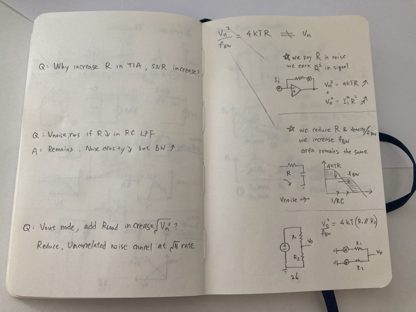
| # | 📍 Question | ✔️ | 💡 Note |
|---|---|---|---|
| #1 | 📐 4kTR is V²/Hz, not Vn | ✅ | PSD, not rms |
| #2 | 📈 TIA: R↑ raises SNR | ✅ | Pay R in noise, earn R² in signal: power SNR ∝ R |
| #3 | 🔁 RC LPF: Vrms if R↓ | ✅ | Unchanged, area is kT/C |
| #4 | 🔌 Add Rload at Vout | ⚠️ | Reduces spot noise only; see §2 |
| #5 | 🧮 "uncorrelated noise cancels at √N" | ❌ | Never cancels; adds in power. Node sees 4kT(R₁∥R₂), the Thevenin R |
Each resistor's noise reaches Vo through the other's divider, and the two add in power. Nothing cancels; the divider just attenuates faster than the noise accumulates. The √N rule is only the special case of N equal resistors in parallel.
Every real node has capacitance, so "does adding Rload reduce the noise?" has two honest answers. Name which one you mean.
| # | 📏 Quantity | 🧾 Units | 🔌 Add Rload | 🔑 Set by |
|---|---|---|---|---|
| #1 | Spot noise, below the RC corner | V/√Hz | ↓ drops | √(4kT·R∥) |
| #2 | Noise over a fixed band below fc | V rms | ↓ drops | √(4kT·R∥·B) |
| #3 | Total integrated noise, 0 to ∞ | V rms | → unchanged | √(kT/C) |
No approximation is thrown away. Every constant cancels exactly.
| # | 🪜 Step | 📐 Expression | ✂️ What cancels |
|---|---|---|---|
| #1 | Resistor PSD | 4kTR [V²/Hz] | |
| #2 | 3 dB corner | fc = 1/(2πRC) | |
| #3 | Noise bandwidth = ∫|H|² df | fc·∫0∞ dx/(1+x²) = fc·π/2 | arctan(∞) = π/2 |
| #4 | Plug in fc | (π/2)·1/(2πRC) = 1/(4RC) | π meets π |
| #5 | Total noise | 4kTR · 1/(4RC) = kT/C | 4 meets 4, R meets R |
Figure 1 · Linear f: slide the brick wall until the areas balance
Figure 2 · θ = arctan(f/fc): the RC curve goes flat
Figure 3 · Quarter circle vs triangle
Figure 4 · Rolling the arc: arc length = wall height
Steeper filters leak less past their corner, so the brick-wall equivalent hugs f3dB. Ranked by excess noise bandwidth (ENBW/f3dB − 1):
| # | 🎛 Filter | 📏 ENBW/f3dB | 📊 Excess |
|---|
Butterworth n: ENBW/f3dB = (π/2n)/sin(π/2n). Two identical real poles: ENBW = 1/(8τ), f3dB = √(√2−1)/(2πτ).
| # | ❓ Prompt | 🗣 Say this |
|---|---|---|
| #1 | Why kT/C? | 4kTR times the noise bandwidth 1/(4RC): the 4 and the R cancel exactly. It is energy over capacitance, no approximation. |
| #2 | Why π/2? | The RC tail past the corner is worth 57% more width: ∫dx/(1+x²) = arctan → π/2. Geometrically, a right triangle on a unit base must be π/2 tall to match a quarter circle. |
| #3 | Add Rload: more or less noise? | Spot noise drops as 4kT·R∥. Total integrated noise on a capacitive node stays kT/C. Name the measurement bandwidth. |
| #4 | Uncorrelated sources? | They add in quadrature, growing as √N. They never cancel; correlated signals grow as N, which is why averaging wins. |
| #5 | TIA: bigger R always better? | Power SNR ∝ R while resistor noise dominates. But R also lowers bandwidth, and at high f the op-amp en·Cin noise takes over. |