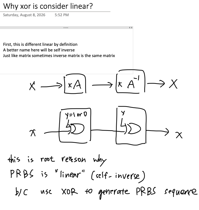
x·A then x·A⁻¹ returns x),
XOR-ing twice with the same y returns the original x.
That is the root reason a PRBS is called "linear": the sequence is generated with XOR.
Worked out below in XOR is its own inverse.A 3-flip-flop LFSR can produce a maximal-length sequence of 23 − 1 = 7 states. That guarantee holds only when the feedback gate is XOR. Swapping in AND or OR breaks the property the guarantee rests on: XOR preserves the difference between any two states as the register evolves. AND and OR destroy it.
Three D flip-flops holding state (b2, b1, b0). On each clock edge the register shifts right and the feedback bit enters at b2:
- feedback
f = b0 ⊕ b2 - next state
(b2', b1', b0') = (f, b2, b1)
Two other tap choices are also primitive for 3 bits. All three give the full 7-state cycle, so choosing between them is routing convenience, not sequence quality.
All seven non-zero states appear exactly once. 000 is the lock-up state and is never entered — so never seed with it.
Not the physics sense of "output proportional to input." In GF(2) it means the update rule respects superposition:
Read it as a claim about differences. Take two states A and B — the same three flip-flops, just two different starting conditions — and call their difference D = A ⊕ B. Clock A and B forward independently, then compare them again. You get exactly the same answer as if you had thrown A and B away and clocked D forward on its own.
The difference evolves as if it were a state in its own right. A better name than "linear" would be difference-preserving.
Starting from A = 101 and B = 011. The right-hand columns compare the difference measured from A and B against the difference clocked forward by itself.
| Clock | State A | State B | D measuredA ⊕ B | D clocked alonestep(D) | Agree? |
|---|---|---|---|---|---|
| t = 0 | 101 | 011 | 110 | 110 | YES |
| t = 1 | 010 | 101 | 111 | 111 | YES |
| t = 2 | 001 | 010 | 011 | 011 | YES |
| t = 3 | 100 | 001 | 101 | 101 | YES |
The difference is not frozen — it moves. What holds constant is that it moves by the same rule the states do. That is the invariant.
Identical starting states, identical shift structure, only the gate changed to f = b0 · b2.
| Clock | State A | State B | D measuredA ⊕ B | D clocked alonestep(D) | Agree? |
|---|---|---|---|---|---|
| t = 0 | 101 | 011 | 110 | 110 | YES |
| t = 1 | 110 | 001 | 111 | 011 | NO |
| t = 2 | 011 | 000 | 011 | 001 | NO |
| t = 3 | 001 | 000 | 001 | 000 | NO |
The seed row agrees trivially — at t = 0 nothing has been clocked yet, so both columns are the same computation. Divergence starts at the first clock edge and never recovers.
Two things go wrong. The difference stops tracking after a single clock, because AND's output depends on the absolute bit values rather than on how the two states differ. And state B collapses into 000 at t = 2 and is stuck there — AND drains bits toward zero instead of circulating them.
XOR applied twice with the same operand returns the original:
1 ⊕ 0 = 1, then1 ⊕ 0 = 10 ⊕ 1 = 1, then1 ⊕ 1 = 0- in general,
(A ⊕ K) ⊕ K = A
Concretely: 1011 ⊕ 0110 = 1101, and 1101 ⊕ 0110 = 1011. Back where you started.
That is the crux of it. The XOR in the feedback path generates the sequence; a second XOR, elsewhere in the system, recovers the difference between two copies of that sequence. Same gate, same algebra, opposite directions. There is no separate decode logic to design — which is exactly why XOR shows up throughout scramblers, BERT receivers, stream ciphers, and CRC hardware.
AND and OR have no inverse. Given a 0 out of an AND gate you cannot recover the inputs, so nothing downstream can undo them.
- Maximal length is 2N − 1. Three flip-flops give 7, four give 15, five give 31.
- Only linear feedback earns that guarantee. Primitive-polynomial theory applies to GF(2) linear systems, and XOR is the only linear two-input gate available.
- Nonlinear feedback is not forbidden, just unpredictable. If you want it, you have to search the state space empirically — there is no theorem to lean on, and lock-up states are common.
- Tap choice is a layout decision. All three primitive 3-bit polynomials give 7 states from any non-zero seed; only the visit order changes.
- Seed with anything except 000. Zero is an absorbing state for XOR feedback.